
[ PID Control For CPU Temperature of Raspberry Pi ]
By Stephen Haesung LEE in raspberry-pi


Introduction
My motivation for PID Control For CPU Temperature of Raspberry Pi came for many reasons such as very hot CPU, very noisy fan’s sound and fast battery consumption because the hot CPU makes the system really unstable while using Raspberry Pi for a long time. So, I have optimized the failing by using PID node on Node-RED. It’s visually helpful for a trainee to understand the PID control system for an educational purpose.
This will cover the basic steps that you need to follow to get started with open sources like PID node, MQTT node in the Node-RED. Also, it’s really painful and hard to tune 3 gains like KP, KI, and KD as manual tuning(Trial and error) method. There are many tuning methods such as Manual tuning, Ziegler–Nichols, Tyreus Luyben, Cohen–Coon, Åström-Hägglund and Software tools such as Simulink in Matlab or Excel PID Simulator (enclosed). I’ve already provided my source codes in the Download List but If you use a different fan, you should tune PID gains because most physical fan’s characteristics are different. You can get more information from the linked web (PID controller).
MQTT(Message Queueing Telemetry Transport) is a Machine-To-Machine(M2M) or Internet of Things (IoT) connectivity protocol that was designed to be extremely lightweight and useful when low battery power consumption and low network bandwidth is at a premium. It was invented in 1999 by Dr. Andy Stanford-Clark and Arlen Nipper and is now an Oasis Standard. I’ve already published about how to approach the MQTT below the linked webs.
http://www.instructables.com/id/Smart-JPEG-Camera-for-Home-Security/
http://www.instructables.com/id/Smart-Gas-Valve-Checker-for-Home-Safety/
Step 1: Table of Contents
Step 0: Introduction
Step 1: Table of Contents
Step 2: Bill of Materials
Step 3: Setting up an acrylic clear case, a fan with Raspberry Pi
Step 4: Programming NodeRED on Raspberry Pi2
Step 5: Setting up MQTT v3.1 on Raspberry Pi2
Step 6: Checking your NodeRED codes with MQTT on Raspberry Pi2
Step 7: Adding & Setting up PID node, Dashboard on Raspberry Pi2
Step 8: Using a dashboard for PID control
Step 9: Tuning PID controller
Step 10: Download list
Step 11: List of references
Step 2: Bill of Materials
- Raspberry Pi2 X 1ea
- Pi-1,2,3 are Possible.
- Installation guide
- Download image files
- Installing VNC : You can connect Raspberry Pi2 with Macbook Pro or Windows.
- Raspberry Pi’s box with Fan X 1ea
- PNP A1015 Transistor X 1ea
- Adjustable resistor(102) X 1ea
- Jumper wires(1m) X 1ea
- Wifi dongle X 1ea
- Description
- If you have Pi-3, it’s unnecessary.
- Android smartphone’s portable battery X 1ea
- Nod-RED software X 1ea
- Free open source
- Use the version pre-installed in Raspbian Jessie image since November 2015
- Installation guide
- MQTT v3.1 software X 1ea
- Free open source
- Installation guide includes at the Step
- Places to buy from?
Step 3: Setting up an acrylic clear case with a circuited fan with Raspberry Pi


Assembly steps
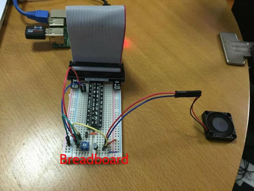
(1) I suggest you should use a breadboard before soldering and wiring all.
(2) Connect the Raspberry Pi2 with a PNP 1015 transistor, a fan, and a variable 102(1k) resistor as shown above in the circuit diagram.
(3) I used a glue gun to attach with the clear case.
(4) Lastly, connect a portable battery with Raspberry Pi2. (Use any portable battery to connect with the same size connector cable on Raspberry Pi2. )
Step 4: Programming NodeRED on Raspberry Pi2


How to start Node-RED on web-browser.
(1) Write down command shown below to a terminal window.
node-red-start
(2) You can find an IP address as below. ‘Once Node-RED has started, point a browser at http://169.254.170.40:1880’ (It depends on your IP address)
(3) Open your web browser.
(4) Copy the IP address and paste on web-browser.
(5) It will display a visual editor of Node-RED on web-browser.
(6) You can start coding with visual editor on web-browser.
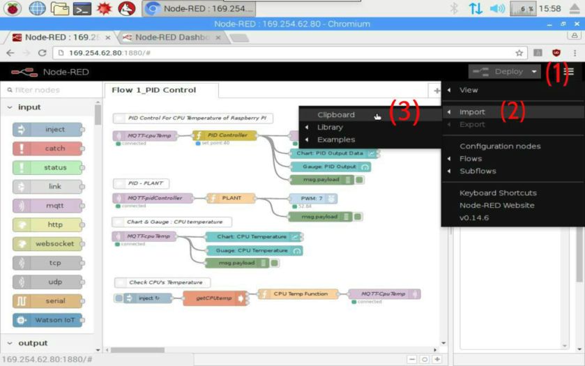
(7) Try dragging & dropping any node from the left-hand side to right-hand side. It’s really easy to code. ( You can conveniently use the visual editor offline as well as online. ) Download the ‘PID_Control_For_CPU_TEM_ver0.5.txt’ file. (1) Click the number (1) at the right-hand side corner shown in NodeRED on web-browser. (2) Click the Import button on the drop down menu. (3) Open the Clipboard shown in the above 1st picture. (4) Lastly, paste the given JSON format text of ‘PID_Control_For_CPU_TEM_ver0.5.txt’ in Import nodes editor.
Step 5: Setting up MQTT v3.1 on Raspberry Pi2
Setting up MQTT v3.1 on Raspberry Pi2
This message broker(Mosquitto) is supported by MQTT v3.1 and it is easily installed on the Raspberry Pi and somewhat less easy to configure. Next we step through installing and configuring the Mosquitto broker. We are going to install & test the MQTT “mosquitto” on terminal window.
curl -O http://repo.mosquitto.org/debian/mosquitto-repo.gpg.key
sudo apt-key add mosquitto-repo.gpg.key
rm mosquitto-repo.gpg.key
cd /etc/apt/sources.list.d
sudo curl -O http://repo.mosquitto.org/debian/mosquitto-jessie.list
sudo apt-get update
Next install the broker and command line clients:
- mosquitto – the MQTT broker (or in other words, a server)
- mosquitto-clients – command line clients, very useful in debugging
- python-mosquitto – the Python language bindings
sudo apt-get install mosquitto mosquitto-clients python-mosquitto
As is the case with most packages from Debian, the broker is immediately started. Since we have to configure it first, stop it.
sudo /etc/init.d/mosquitto stop
Now that the MQTT broker is installed on the Pi we will add some basic security.
Create a config file:
cd /etc/mosquitto/conf.d/
sudo nano mosquitto.conf
Let’s stop anonymous clients connecting to our broker by adding a few lines to your config file. To control client access to the broker we also need to define valid client names and passwords. Add the lines:
allow_anonymous false
password_file /etc/mosquitto/conf.d/passwd
require_certificate false
Save and exit your editor (nano in this case).
From the current /conf.d directory, create an empty password file:
sudo touch passwd
We will to use the mosquitto_passwd tool to create a password hash for user pi:
sudo mosquitto_passwd -c /etc/mosquitto/conf.d/passwd pi
You will be asked to enter your password twice. Enter the password you wish to use for the user you defined.
Testing Mosquitto on Raspberry Pi
Now that Mosquitto is installed we can perform a local test to see if it is working: Open three terminal windows. In one, make sure the Mosquitto broker is running:
mosquitto
In the next terminal, run the command line subscriber:
mosquitto_sub -v -t 'topic/test'
You should see the first terminal window echo that a new client is connected.In the next terminal, run the command line publisher:
mosquitto_pub -t 'topic/test' -m 'helloWorld'
You should see another message in the first terminal window saying another client is connected. You should also see this message in the subscriber terminal:
topic/test helloWorld
We have shown that Mosquitto is configured correctly and we can both publish and subscribe to a topic.When you finish testing all, let’s set up below that.
sudo /etc/init.d/mosquitto start
Step 6: Checking your NodeRED codes with MQTT on Raspberry Pi2


When you will use the JSON format of the ‘PID_Control_For_CPU_TEM_ver0.5.txt‘ on Node-RED, it’s automatically set up & coded each data. I have already set up the each data in each node.
(1) Click each node.
(2) Check information inside each node has been prefilled.
(3) Please don’t change the set data. (The above can be customized for more advanced users.)
Step 7: Adding & Setting up PID node, Dashboard on Raspberry Pi2
Searching the Nodes
Node-RED comes with a core set of useful nodes, but there are a growing number of additional nodes available for installing from both the Node-RED project as well as the wider community. You can search for available nodes in the Node-RED library or on the npm repository.
- For example, we are going to search ‘node-red-node-pidcontrol‘ at the npm web. Click here.
- Then, we are going to install npm package, node-red-node-pidcontrol, node-red-dashboard on Raspberry Pi.
To add additional nodes you must first install the npm tool, as it is not included in the default installation. The following commands install npm and then upgrade it to the latest 2.x version.
sudo apt-get update
sudo apt-get install npm
sudo npm install -g npm@2.x
hash -r
cd /home/pi/.node-red
- For example, ‘npm install node-red-{example node name}’
- Copy the ‘npm install node-red-node-pidcontrol’ from the npm web. Paste it on a terminal window.
- Ex: node-red-dashboard, and node-red-node-pidcontrol
npm install node-red-node-pidcontrol node-red-dashboard
- You will need to restart Node-RED for it to pick-up the new nodes.
node-red-stop
node-red-start
- Close your web browser and reopen the web browser.
Step 8: Using a dashboard for PID control


The dashboard is a visual UI tool like gauge, chart. There is a basic tutorial of a Node-RED dashboard using node-red-dashboard. http://developers.sensetecnic.com/article/a-node-red-dashboard-using-node-red-contrib-ui/
How to use the dashboard on Raspberry Pi.
(1) Click the number (1) of the gauge node.
(2) Set the group property.
(3) Set the properties from (3) to (7) shown from above the picture.
(4) Click the number (8) to go the dashboard window.
(5) Press the number (9) to display the gauge on the web browser.
(6) You can see the gauge which displays ‘40.1’ from the web browser.
(7) The chart to display on the web browser is same as the gauge (1 – 9 steps).
Step 9: Tuning PID controller


There are many tuning methods such as manual tuning, Ziegler–Nichols, Tyreus Luyben, Cohen–Coon, Åström-Hägglund and software tools such as Simulink in Matlab or Excel PID Simulator(enclosed). I’ve used 2 tuning methods like manual tuning, Ziegler-Nichols method and software tools such as Matlab, Simulink, and Excel. (According to Wikipedia: PID Controller)
- Manual Tuning(Trial and error)
How do the PID parameters affect system dynamics?
We are most interested in four major characteristics of the closed-loop step response. They are
– Rise Time: the time it takes for the plant output y to rise
– Overshoot: how much the peak level is higher than the steady state, normalized against the steady – state.
– Settling Time: the time it takes for the system to converge to its steady state.
– Steady-state Error: the difference between the steady-state output and the desired output.
(NT: No definite trend. Minor change.)
How do we use the table?
Typical steps for designing a PID controller are Determine what characteristics of the system needs to be improved.
– Use KP to decrease the rise time.
– Use KD to reduce the overshoot and settling time.
– Use KI to eliminate the steady-state error.
– This works in many cases, but what would be a good starting point? What if the first parameters we choose are totally crappy? Can we find a good set of initial parameters easily and quickly?
- Ziegler–Nichols method
– Ziegler and Nichols conducted numerous experiments and proposed rules for determining values of KP, KI, and KD based on the transient step response of a plant.
– They proposed more than one methods, but we will limit ourselves to what’s known as the first method of Ziegler-Nichols in this tutorial. It applies to plants with neither integrators nor dominant complex-conjugate poles, whose unit-step response resemble an S-shaped curve with no overshoot. This S-shaped curve is called the reaction curve. This S-shaped curve is called the reaction curve.
– The S-shaped reaction curve can be characterized by two constants, delay time L and time constant T, which are determined by drawing a tangent line at the inflection point of the curve and finding the intersections of the tangent line with the time axis and the steady-state level line.
– The Ziegler-Nichols Tuning Rule Table
Using the parameters L and T, we can set the values of KP, KI, and KDaccording to the formula shown in the table above.
These parameters will typically give you a response with an overshoot about 25% and good settling time. We may then start fine-tuning the controller using the basic rules that relate each parameter to the response characteristics. KP, KI, and KD based on the transient step response of a plant.
- PID tuning software
– Matlab: PID Controller Tuning
– Simulink: PID Controller Tuning
– Excel PID simulator
– Etc
- PID control VS On/Off control
– On/Off control: An on-off controller is the simplest form of temperature control device. The output from the device is either on or off, with no middle state. An on-off controller will switch the output only when the temperature crosses the setpoint. For heating control, the output is on when the temperature is below the setpoint, and off above setpoint. Since the temperature crosses the setpoint to change the output state, the process temperature will be cycling continually, going from below setpoint to above, and back below. In cases where this cycling occurs rapidly, and to prevent damage to contactors and valves, an on-off differential, or “hysteresis,” is added to the controller operations. This differential requires that the temperature exceeds setpoint by a certain amount before the output will turn off or on again. On-off differential prevents the output from “chattering” or making fast, continual switches if the cycling above and below the setpoint occurs very rapidly. On-off control is usually used where a precise control is not necessary, in systems which cannot handle having the energy turned on and off frequently, where the mass of the system is so great that temperatures change extremely slowly, or for a temperature alarm. One special type of on-off control used for alarm is a limit controller. This controller uses a latching relay, which must be manually reset, and is used to shut down a process when a certain temperature is reached.
– PID control: This controller provides proportional with integral and derivative control, or PID. This controller combines proportional control with two additional adjustments, which helps the unit automatically compensate for changes in the system. These adjustments, integral and derivative, are expressed in time-based units; they are also referred to by their reciprocals, RESET, and RATE, respectively. The proportional, integral and derivative terms must be individually adjusted or “tuned” to a particular system using trial and error. It provides the most accurate and stable control of the three controller types, and is best used in systems which have a relatively small mass, those which react quickly to changes in the energy added to the process. It is recommended in systems where the load changes often and the controller is expected to compensate automatically due to frequent changes in setpoint, the amount of energy available, or the mass to be controlled.
Step 10: Download list


Step 11: List of references
- A developer’s guide to the Internet of Things (IoT) by IBM
- MQTT.org: Version 3.1.1 becomes an OASIS Standard
- MQTT.org: Documentation
- Eclipse Paho
- What is Really Small Message Broker(RSMB)? (IBM)
- http://stanford-clark.com/
- The House That Twitters – Andy Stanford-Clark
- Node-RED.org: Documentation
- Node-RED: Running on Raspberry Pi
- Node-RED: Writing Functions
- JavaScript Reserved Words
- Node-RED: Node-RED Library
- RUN KIT: PID controller

Hi Stephen, I love your blog. And this one is great tutorial. I want to try.
Would you mind to help me if i encounter an problem?
Thanks
LikeLike
Thanks. I can help you whatever.
Have fun with my blog.
LikeLiked by 1 person
Oke, thanks.
LikeLike
is the potentiometer acting like a temperature sensor?
LikeLike
This is a adjustable resistor. The temperature sensor is there in the ARM processor.
LikeLike